Quantcast
Channel: Terminal AutoCAD
Viewing all 46 articles
Browse latest View live

Blog News

$
0
0

Sorry for the lack of posts over the past week or so. I have been in the Autodesk Inventor world... I do have some Inventor Cable and Harness posts planned. And now this week I have moved into the world of AutoCAD Plant 3D. I sure wish some of Plant's features would make their way over to the Electrical side! Plant 3D is a very slick software package.

As for this blog, I have been opening many of the past posts and reposting them under their proper categories. For example: Creating a custom PLC style in AutoCAD Electrical was NOT listed under PLC. My categories have kind of evolved into what they are now and I plan on sticking with this latest set. I'm sure a few new ones will be added in time.

image


Presetting The Surfer's Zoom Distance in AutoCAD Electrical

$
0
0

The Surfer's zoom distance is typically perfect in the schematic. However when moving into panels it tends to zoom in much to far. If you have a panel template, this is something that can be set there as well.
Panel Org Zoom

Simply open your panel template and place a sample panel footprint. Then surf to it. Use the Zoom In/Out buttons as needed and then press Zoom Save. Delete the footprint and purge it from your template. That's it! Save this over your existing panel template. If you want to know where this setting is stored, press the 'Read More' link.

This data is stored as Xdata on the wd_m block. Typically this block is store at 0,0. However it has no geometry or visible attributes. That makes it quite hard to select. The easiest way to see/select this block is to toggle ATTMODE to 2. This shows ALL attributes in all blocks. My wd_m block is shown below after switching ATTMODE to 2.
image     image

Now that we can see the block, we need to start the Xdata Editor to view and create Xdata. You find this from the Project tab under the Other Tools panel's dropdown.image

After starting the command, click on the wd_m block. The default value is 2 (64 if metric). A larger number will zoom out more.
If you do not have the VIA_WD_SURF_ZOOM name, press Add New and add it. This value is missing until a 'Zoom Save' has been pressed on the Surfer. From that point on this Xdata is stored here.
 image

Listed below are several zoom distances that may help you decide what value to choose. Listed below, and in this order, are SURF_ZOOM's 1.5, 2, 6, and 12. Rather than messing with numbers, you can always press the Zoom In and Zoom Out buttons and then Zoom Save button once you like the zoom distance. That's what is shown below... three different zoom distances.


1.5 2  6  12

Managing Projects Inside of AutoCAD Electrical

$
0
0

imageTo take advantage of many of the features of AutoCAD Electrical you MUST be using project files. What are a few of these "features"? Well, any drawing to drawing relationships such as, source and destination arrows, parent-child relationships, and the Automatic Title Block Update cannot function without a project file. Basically anything that involves multiple drawings interacting together.

The project file is simply a text file that uses a .wdp extension. image The name of the file is the actual project name. This text file stores the project properties, project descriptions, drawing descriptions, as well as a list of its drawings and their locations.

In release 2013 the project file also stores the subfolders created under the project.
image
The project file is typically stored in the same folder as the project drawings. imageHowever it is not necessary for all drawings to live inside this folder. If a drawing doesn't live inside the project folder, the project file will store the relative path from the project file to the drawing.

The Project Manager

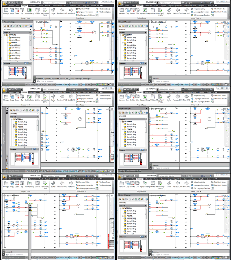
imageThe Project Manager is the palette used when working with anything project related. If this pallet is missing, press the Manger button on the Project tab to bring it back on screen. This is like any other AutoCAD palette; it can be docked to the side as well as minimized and expanded as needed. In the video loop below I am showing how to dock/undock and minimize/expand a tool pallet.
Project Manger Palette
The Project Manager is made up of four parts.

The top toolbar.

image 

The project menu.

image


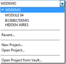
This menu is accessed by clicking on the down arrow button. image This menu shows the name of the active project as well as a list of the currently loaded projects. Clicking on one of the project names will make it active. We will talk more about "active" projects in a bit. There is also a recent option that shows a quick menu of recent projects, loaded and unloaded, for quick selection. Selecting a project from the Recent menu will load it into the Project Manager and make it the active project.


The project drawing area.

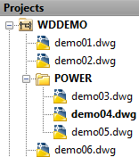
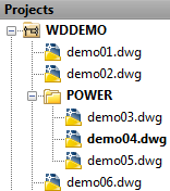
imageIn this area you can view, and open, the drawings listed under any of the loaded projects. The active project is always bold and at the top of the list. The active project is the current project the software is working in. Create a project wide BOM and you will get a BOM of the "active" project regardless of what drawing you have loaded. The "active" project is monitored for changes that must take place on other drawings. Such as source and destination arrows, parent child relationships, footprints, and wire numbers. Because of this you must make sure you always have the correct project set as the "active" project or many commands will not function as expected.

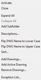
Double clicking on any drawing will open it. Double clicking on a project or folder will expand or collapse it. To set a project as "active" you must right click on it and choose Activate. Active Project's Right Click Menu
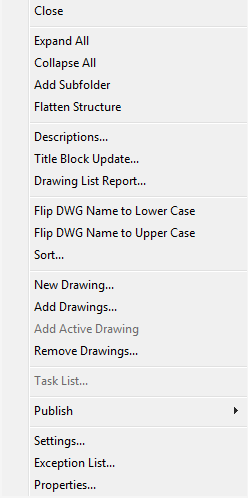
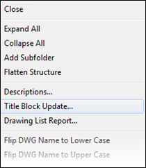
Right clicking on the active project offers the following options. (See image on right)

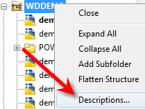
Here you can add or remove drawings, change the order of the drawings (2013 supports drag and drop), create a drawing list report, add subfolders (2013), start the title block update command, access the project properties and more. Closing a project will remove it from the Project Manger palette.

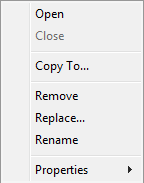
Right clicking on a drawing in any project offers the following options.
image
Removing a drawing from a project will not deleted the actual dwg. It will only remove it from the project's drawing list. From here you can also access this drawings properties.

Rename is the proper way to change the dwg's file name. If you use Windows Explorer to rename several drawings, the project will error on open and require a manual relinking of all renamed files. Using the Rename open will update the project file as well as rename the actual dwg files. You can not rename a file that is currently open. A 'Renamed Failed' error will appear.


Right clicking on a project that is NOT active gives this menu.
image 
At the top of the menu is Activate. Choosing this will make the selected project the active project.

Close will remove this project from the Project Manager. It can always be opened again if needed.

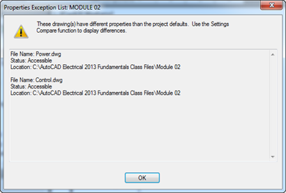
The Exception List shows a small report of which drawings properties do not match their project's properties.
image


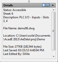
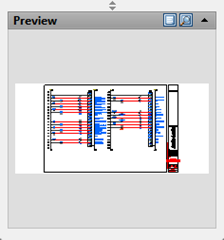
And finally the project/drawing info area.

 image  image

Creating a New Project

image

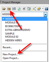
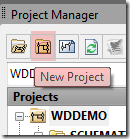
There are two ways to start the New Project command. One of them is on the Project Manager's top toolbar image, the other is under the Project Menu. (see image on left)

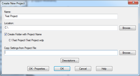
imageSelecting one of these brings up a dialog that will create the project folder and the project file (wdp) itself. Once created it will automatically be listed as the active project.

Simply give the new project a name and a location. If you have an existing project you wish to copy project properties from, you can select that here as well.

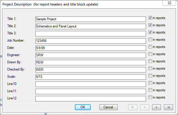
Press the Descriptions button to add project descriptions.
Pressing OK will create the project, and make it active. Pressing
OK - Properties will do this as well but will also display the Project Properties dialog.

This is an empty project so double clicking on it in the project manager will do nothing. You now need to add drawings or create new ones.

Opening Exiting Projects

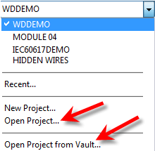
imageStarting in release 2012 an Open Projectimagebutton is on the Project Manager's toolbar. Before that 'Open Project' was selected from the Project Managers project menu. (see image on left)

If any drawings are missing from the project, you will be given the opportunity to locate the missing drawings and the project file will update as needed.

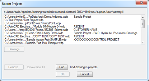
imageThe Recent option will open closed projects as well. Only the past 30 projects are stored here. For more info on this text file (lastproj.fil) see this blog post. Recent Projects

Project Descriptions

imageThese descriptions can be pushed to title block attributes using the Title Block Update utility. If the 'in reports' box is checked, that description line can be pushed as a header in most reports.

More about the Title Block Update and the Project Description Labels can be found here. Title Block Update - The Basics

image

Project Properties

The properties that show this symbol image are project specific. The properties that have this symbol image are drawing specific. The drawing properties will always be honored before the projects. Why would we want that? Well a point to point cable drawing may be numbered sequentially while all other drawings are ladder reference. There are tools available to push the projects 'drawing' properties down to any, or all, drawings. Drawing properties can also be pushed down a single property at a time. 

Plotting a Project

image

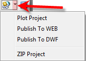
Pressing the Plot button on the Project Manager's toolbar provides a menu of various publish options. I already have a blog post about the Plot Project options. Batch-Plotting-a-Project

For the ZIP Project utility to work, you must specify a compression utility in the wd.env file.


Subfolders

image

image


Starting in release 2013 subfolders can be created in the Project Manager. Subfolders allow another way of managing drawings inside of a project. Drawings can be "drag and dropped" in and out of these subfolders.

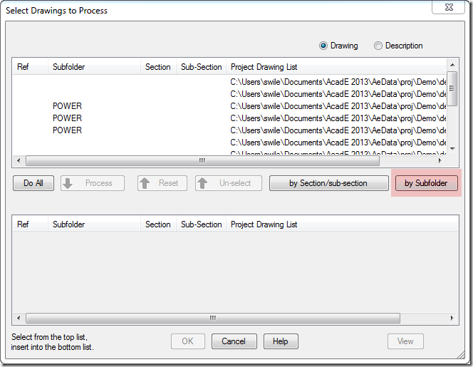
When running project wide utilities, subfolders is a new selection/sorting option. (see image on right)

For example I can now plot all drawings by subfolder, or create a BOM of all drawings by subfolder.

Other Project Wide Tools and Utilities.

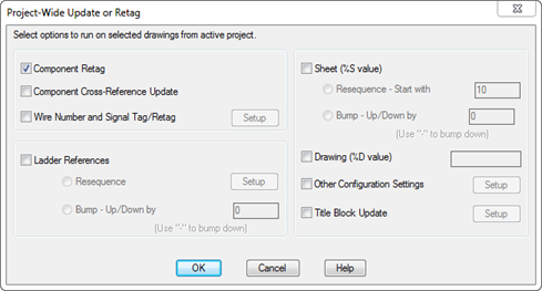
The Project-Wide Update/Retag image tool is available from the toolbar on the Project Manager as well on the ribbon's Project tab. This utility awesome for making mass changes after updating project and drawing settings. From one dialog box you can retag components, update wire numbers, resequence ladders, update sheet numbers, as well as update title blocks. This will do everything that is needed, in the proper order, project wide! Each of these are individual commands but this dialog will run them all back to back.
image
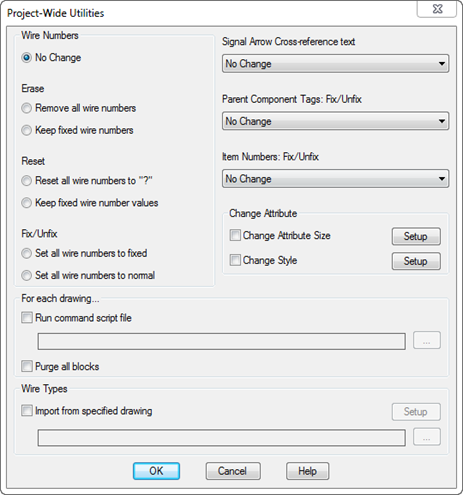
The Project Utilities image, from the Project tab, is another nice project wide tool. Once a project is actually wired, all wire numbers and components should be fixed to keep future edits from changing existing tags/numbers. This utility can fix/lock wire numbers, source/destination arrows, component tags, and item numbers project wide. It can also change them all back to normal should this project ever be copied for a new design.  image

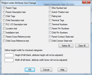
Checking the Change Attribute Size box allows a project wide change of many default Electrical attributes. If a certain client wants the DESC text half size, this utility is for you.

If you want to change an attribute's height for all projects, you really should update the entire symbol library rather than depend on this utility on every project. There's a utility for that as well.
  image


If you have a script you need to run on all drawings, this utility can run it project wide with no setup.

Starting with release 2012 Wire Types can be pulled from a selected drawing to all drawings project wide.

When logged into Vault, status icons show to the left of each drawing. These circles show the status of the files in your workspace against the the versions in Vault.

Copy Project

From the Project tab Copy Projectimage starts a wizard that walks you through copying an existing project to a new name with all new drawing names.

Project Tips

Close unused projects. Keep only the projects you are actively working on loaded in the Project Manger. When AutoCAD Electrical starts it verifies that every drawing, in every loaded project, is still in place. Having 20+ projects loaded can cause significant delays each time Electrical starts.

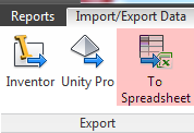
imageRather then edit the project file using Notepad to change mass drawing descriptions, consider exporting the drawing settings using the Export Data to Spreadsheet utility. On import the project file will immediately update and all drawings will see the new changes. I have seen people struggle with getting Electrical to see the changes that happened directly in the wdp file.

Adding Wire Numbers to Symbols

$
0
0

You may have symbols that require showing the wire number at each wire connection. This would be a manual process for each symbol. However adding an additional _X#TERM## attribute eliminates that need.

Note the underscore in front of the tag.
image

Here I simply copy and pasted the original wire connection attributes. I then added the underscore and then made them visible.
image    
image
In this example I made my extra wire numbers font size 0.100 where everything else is 0.125.

And after an 'Swap/Update Block' and a new 'Wire Numbers' through the project, here it is!

image

Creating Keyboard Shortcuts in AutoCAD Electrical

$
0
0
Having started using AutoCAD at release 10 I’m partial to hotkeys. However the marking menu has broke the right click menu/hotkey ability. For example I would right click on a component and then press ‘E’ and Edit Component would trigger from the right click menu. I know the marking menu eliminates the need for the hotkey… simply drag straight up and the command starts. But hey, old habits die hard right.
I decided to map some custom hotkeys. Most of the default alias keys are commands that are not used in AutoCAD Electrical. Take ‘E’ for example. By default this is Erase. It may make more sense to have that as Delete Component or Edit Component. Below are the steps needed to modify AutoCAD’s aliases. You may wish to keep the default aliases and add and ‘E’ in front of all your new Electrical aliases. Like EE for Edit  Component and ED for Delete Component

Method 1

imageIf you have the Express Tools installed, the Command Aliases command is the easiest way to find, and edit, this file. If the Express Tools are not installed you will need to run through the Add/Remove programs and check the Express Tools box.

Be sure to File\Export a copy as a backup before you start messing the file… you know, just in case.
image

This dialog is pretty straight forward. Find the alias you wish to edit and press Edit. Press Add to add a new one.
To find the Electrical command name hover over the icon and the full command name should be in the resulting tool tip.
image
Another way to find a command name… after starting the command press esc and then right click somewhere in model space. Select Recent Input from the right click menu.
image

Method 2

If Express Tools is not an option then here is the manual method.
  • Make a backup of the following file
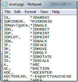
    • C:\Users\<username>\appdata\roaming\autodesk\autocad electrical 2013\r19.0\enu\support\acad.pgp
    image
  • Open acad.pgp with a text editor like Notepad or Wordpad
    • Make any necessary changes.
    image 
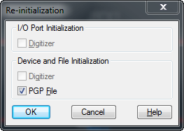
  • REINIT or restart Electrical to test the new aliases.
image

Display of Internal Part Numbers On Symbols – AutoCAD Electrical

$
0
0
imageLast week a user asked me how to push the custom USER data to symbols. He created USER1 and USER2 attributes and then edited the catalog data expecting it to update. However this information is not pushed from the database. CAT and MFG are the only columns that push to symbols. The rest of the columns are pushed to reports but not to symbols.
So the question is… Is this possible? Yep. And you already have access to it. It’s in the AutoCAD Electrical help system. It’s in the form of a sample AutoLISP utility in the "API" section of the help under Section F: ace_get_cat_data Function. The text is at the bottom of this post if you can’t find it… I can’t seem to locate the API Help in release 2013.
This LISP is currently pulling USER1, USER2, and USER3 columns from the catalog and pushing them out to selected symbols with the same named attributes.
 
You could easily edit this script and modify it to push any other columns by simply modifying the existing code or adding a few new lines. The function c:ace_get_cat_data pushes out the data in list form. The help shows what order the columns are reported in. And the LISP refers to the columns by number in the order each column is listed in. USER1 is 12.
So
          (if (/= (nth 12 cat_rec) "")
captures the 12th number in the function report and
          (c:wd_modattrval ben "USER1" (nth 12 cat_rec) nil)Pushes that same 12th value into the USER1 attribute of the selected block.
I posted a copy of this LISP here:
Automatic Display of Internal Part Numbers on Electrical Components.lsp
APPLOAD it and then type user_cat_2_symbol and press enter to run the LISP. 
; Extracted from AcadE "Electrical Help"> "API"> "ace_get_cat_data"
;
(defun c:user_cat_2_symbol ( / x xx cat_rec ben blknam
                               mfg cat assycode)
  ; Utility to populate picked component with USER1/USER2/USER3
  ; values pulled from catalog lookup file
  ; Prompt user to pick each schematic or panel component to process
  (while (setq x (entsel "\nPick component:"))
    (setq ben (car x)) ; Extract entity name of picked object
    ; Look for "CAT" attribute or CAT xdata value on the entity
    (if (AND (setq cat (c:wd_get_pnlval ben "CAT"))
             (/= cat ""))
      (progn ; Non-blank CAT value found, okay to continue
        (setq mfg (c:wd_get_pnlval ben "MFG"))
        (setq assycode (c:wd_get_pnlval ben "ASSYCODE"))
        (setq blknam (c:wd_get_pnlval ben "WDBLKNAM"))
        ; If not WDBLKNAM then use the block insert's block name
        ; to use for table selection within the default_cat.mdb
        ; catalog lookup file.
        (if (OR (not blknam)(= blknam ""))
          (progn ; get actual block name
            (setq blknam (cdr (assoc 2 (entget ben))))
        ) )       
        ; Do catalog lookup on the target MFG/CAT/ASSYCODE combination
        (setq x (c:ace_get_cat_data nil mfg cat assycode blknam))         
        (if x  ; some data returned, use only first or only record
               ; returned (which will be the main part number). Discard
               ; any sub-assembly records (which would follow the first
               ; or main part number record of returned data).
          (progn
            (setq cat_rec (car x)) ; get first (or only) record
            ; nth7=catalogdesc, 8=query1, 9=query2,....14=user3
            (if (/= (nth 12 cat_rec) "") ; USER1 value
              (progn ; non-blank USER1 value, write out to USER1
                     ; attribute on block insert (assumes that
                     ; attribute name USER1 exists on the block
                     ; insert!)
                (c:wd_modattrval ben "USER1" (nth 12 cat_rec) nil)
            ) )
            (if (/= (nth 13 cat_rec) "") ; USER2 value
              (progn ; non-blank USER2 value, write out to USER2
                     ; attribute on block insert
                (c:wd_modattrval ben "USER2" (nth 13 cat_rec) nil)
            ) )
            (if (/= (nth 14 cat_rec) "") ; USER3 value
              (progn ; non-blank USER3 value, write out to USER3
                     ; attribute on block insert
                (c:wd_modattrval ben "USER3" (nth 14 cat_rec) nil)
            ) )
        ) )
    ) )
  )
  (princ)
)

Easy Simplified Catalog Database – AutoCAD Electrical

$
0
0

This question just came in… “Stan is there a way to export all the parts currently in a drawing set into its own small data base because we use the same parts over and over, and the ACAD Electrical data base is just to big to be searching over our network.”

This is not the first time I have been asked this. And in fact there is a neat little utility that does just this. It’s kind of hidden under the Other Tools drop down.
image
 

image


It will create ALL of the family tables even if no catalog entries are needed. The default location is the active project file. However this file could just as easily replace your default catalog.

Hope this helps.

Mechanical Applications for AutoCAD Electrical


Adding the Missing Manufactures to AutoCAD Electrical’s Catalog Database

$
0
0
image

This question keeps coming up. It’s on the Autodesk Discussion Groups, its a call I have answered several times on IMAGINiT’s support desk, and it was just posted on our own discussion group… Productivity Now Discussion Forum - Electrical Product Catalog Post

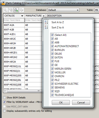
The default install of AutoCAD Electrical only includes a few manufactures. If pressing the catalog Lookup button only shows a few manufactures, my guess is the others aren't installed.

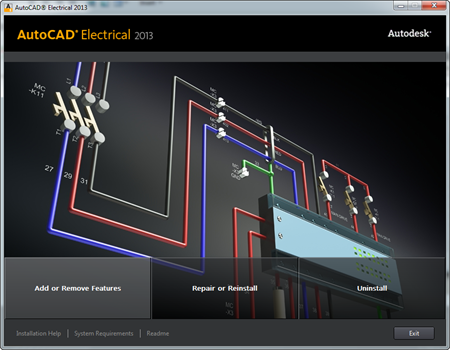
Go to the “uninstall a program” dialog from Windows Control Panel. Select AutoCAD Electrical and the press Uninstall/Change.
 image  image

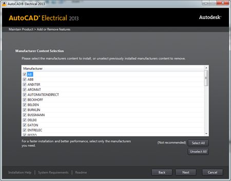
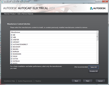
Shown below are the dialogs for both Electrical 2013 and 2014. Press Add or Remove Features.
image    image

Select all desired manufactures and then press Next through the next few dialogs. Be prepared to insert the media or point the installer to the downloaded (and extracted) files.
image
    image

Creating a Table of Contents or Drawing List Report – AutoCAD Electrical

$
0
0
AutoCAD Electrical has a built in Drawing List Report that can report any of the drawing properties within the active project.
image
It’s a little unusual in that its nowhere to be found in the reporting tools. Instead its on the active project’s right click menu. image
image
  So first of all a project file is needed. Simply create a new project file. image Save it in the same location as the drawing files. This will make it the active project automatically. In this example I’m assuming you are all ready using the Title Block Update utility. In that case the drawing properties are already filled out. If not, right click on any of the drawings and choose Drawings/Drawing Properties from the menu. The Drawing Property dialog is shown to the right. Any of these properties as well as file name, last modified date and time and more can be pushed to a table or exported.

Creating a Drawing List Report

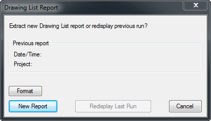
After all drawing have been added to the project and all properties have been filled in, right click on the active project and choose Drawing List Report. Press New Report.
image

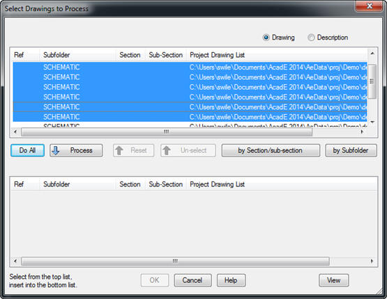
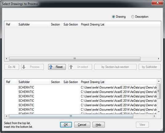
Like every other '”project wide” tool, there is an option to choose what drawings are to be included in the report. Simply press ‘Do All’. This pushes all of the drawings down into the process side. Then press OK.
image  image
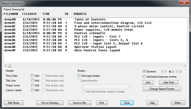
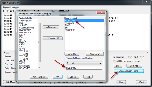
The following is a quick preview of what fields are currently selected, the order they will report, and they column headings. Each of these will be explained below. Pressing ‘Put on Drawing’ will take us to the Table Generation Setup dialog.
image
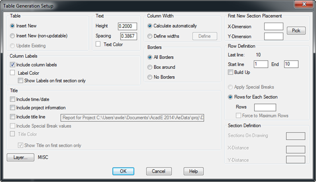
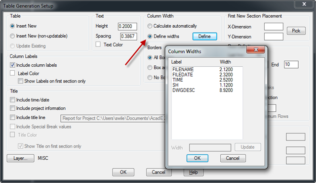
Here column widths, text heights, table layer, as well as a number of other table settings are specified. Pressing OK closes all dialogs and allows table placement on the drawing.
image
image
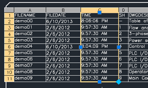
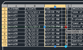
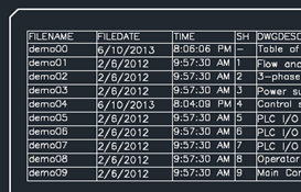
The table can be manipulated as needed and future updates of drawing properties will not update the existing table. For example: I would like the TIME column slightly narrower. That change can happen using normal AutoCAD methods. As drawings are added or removed simply rerunning the Drawing List Report will update THIS tables values. It does not delete this table and place a new one.
imageimageimage

The Options

From the Report Generator dialog there are a number of options. ‘Change Report Format’ not only all drawing properties and a number of file properties, it also shows all attributes of the active title block! The order of the selected fields determines the order they will be displayed in the table. Use the ‘Move Up’ and ‘Move Down’ buttons to change the order.
Each columns header can be modified here as well. Note the arrows.
image
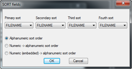
imageModifying the ‘Sort’ order is another option. Select any field from one of the ‘Sort Columns’ and the table will update accordingly.
image
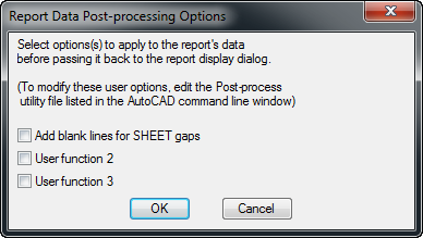
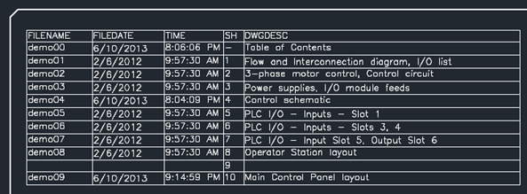
‘User Post’ options are customizable scripts that can be run on the report data outside of the generator dialog. One script is included to get you started and it’s actually a pretty useful one. It adds in additional rows to the table if there are any gaps in the sheet numbers. See row nine below.
Modifying or adding new post processing utilities is a another post for another day.
image image
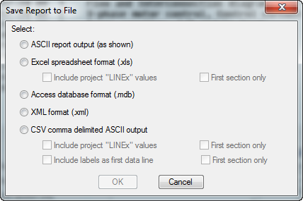
And finally when using the ‘Save to File’ button here are the available export types.
 image 
The only real option that should be pointed out on the Table Generation Setup dialog is the ‘Column Widths’ option. Using this defines column widths before actually placing the table on the drawing.
image

Drawing List Template

Rather than setup a settings file and constantly placing new tables, why not place a Drawing List table and customize as needed? Shading, borders, font, colors, ect are all set using AutoCAD’s Table Styles. The table style being used is ACE_TABLE_1.image  Save the drawing as a template (.dwt) and then insert it whenever a drawing list is needed. Rerun the report and when placing the table ‘Use Existing’ will automatically be selected. The table from the template will update.
image  image

Modifying Attributes In Existing Blocks – AutoCAD Electrical

$
0
0

Anyone modifying existing block attributes has run into the mysteries of how to update the existing blocks on the drawing. Reinserting the block doesn't update the attributes. I should be using Swap/Update block. However when testing I tend to keep the changes inside the test drawing using embedded blocks. Doing this means the existing occurrences of this updated block must have their attributes synchronized.
image

The only problem I have with this method of updating existing blocks is having all attributes return to the blocks default layer. Today I learned when using the Swap/Update block all attributes are placed back on the proper Electrical layer. This is a great little discovery. Now I can continue editing the block within the drawing until I’m happy with it, then WBLOCK it back out to the library. Following that up with an Swap/Update puts existing blocks back in order.

   imageimage

Running a LISP, or Command, on File Open - (Fix_Me)

$
0
0

You can set a LISP utility to run each time you open a drawing from the Project Manager. This is set in the wd.env file. Look for the line that starts with *WD_OPEN_DWG.
         <<Link to my post about the wd.env file>>

“How do I mark a symbol/wire that has a problem, or missing information, and later quickly find it?” Last week this question came up again.

Below is some code that you can find inside of Electrical’s help as sample LISP code. Simply copy and paste it into a text file and save the file as Fix_Me.lsp. APPLOAD this file.

(defun c:fix_me ( / ss en ed xy)
  ; Look for any block insert on the drawing with a block name of "FIX_ME"
  (setq ss (ssget "_X"'((-4 . "<AND")(0 . "INSERT")(2 . "FIX_ME")(-4 . "AND>"))))
  (if (/= ss nil)
    (progn ; one or more found. Zoom up on the first one found
      (setq en (ssname ss 0)) ; entity name of first or only block
      (setq ss nil) ; release the selection set
      (setq ed (entget en))
      (setq xy (cdr (assoc 10 ed))) ; block insertion point
      (command "_.ZOOM""_CENTER" xy 1.0)
      (princ "\nThis needs attention!!!\n")
  ) )   
  (princ)
)

Typing ‘fix_me’ will now run the script which zooms in on the first block named fix_me that the script finds. So create a block named fix_me and give it attributes for notes as well as all symbol attributes. This fix_me symbol can then be used when a needed symbol is missing and the engineer is waiting on the CAD Admin to create it. Once the new symbol is finished the fix_me symbol can be swapped (Swap/Update Block) with the new one. Values in the attributes will carry across to the new symbol. It could also be placed off to the side of a symbol with missing catalog info, or anything else the engineer is unsure of at the time of placement.

So once the LISP file and block are created, why not run them each time a drawing is opened? This takes us back to the WD_OPEN_DWG line in the wd.env file. If your block and LISP files are both named fix_me replace the default *WD_OPEN_DWG line with this…
WD_OPEN_DWG,(if(not c:fix_me)(if(setq x(findfile "fix_me.lsp"))(load x)))(if c:fix_me (c:fix_me))

Pretty slick right.

Surfing a Project Using Wild Cards – Fix_Me 2

$
0
0

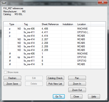
imageLast week while discussing the ‘fix_me’ LISP with Jeff D. from Harris Corporation, Jeff suggested skipping the script all together and instead filling in the fix_me’s block TAG1 default prefix with fix_me-. Then later surfing the project for any symbols with a TAG starting with ‘fix_me’. This is a great idea.

Create a new symbol called fix_me and add it to the icon menu. Make sure to add fix_me- to the TAG1 attribute as the default prefix. Now it can be inserted like a normal symbol. The tag will take on fix_me- as a prefix and whatever the proper reference number should be. ex. fix_me-101

Now to surf project wide for any symbols starting with fix_me….

Start the Surfer from the Project tab.
image 
The command is asking you to select something for the Surfer to tract. Instead press Enter.
image

imageimage
From this dialog you can use many wild cards to search the entire project for components, catalog numbers, wire numbers, and item numbers.

Add fix_me* to the Component tag field and press OK. Project wide all components who’s TAG starts with fix_me are shown. From here I can surf to each one.

This gives a list of all components in one list. Something the ‘fix_me’ script does not. However users will need to remember to run this from time to time. Where as the ‘fix_me’ script runs every time the drawings is opened.

Just another option. I thought it was a cool idea. Thanks Jeff.

Swapping Entire Symbol Libraries Project Wide

$
0
0
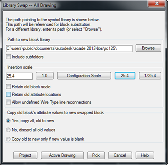
Having completing an entire project using JIS symbols, you are told the client would rather have JIC style symbols. Never fear ‘Swap/Update Block’ saves the day.
image
imageIf you are planning on going project wide, I would recommend making a backup first.
Active drawing is better for testing your selection to verify results before going project wide. If your not happy with the results simply close the drawing and don’t save. Be sure to set the proper scale. Some library styles are in metric other are not.
image
Here is a before and after example after switching from JIS to JIC.
imageimage
The tool in action…
Library_Swap

Flattening 3D Models Into 2D Footprints – FLATSHOT

$
0
0

It seems many vendors are no longer offering 2D drawings of their components and are instead posting 3D models. This makes for a very large drawing and affects overall performance.

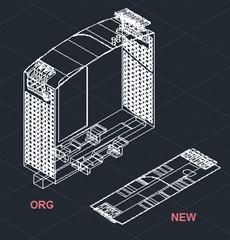
image

imageThis isn’t a problem. Using FLATSHOT, an existing AutoCAD command, the 3D model can easily be broken into 2D top and side views. Insert the model into a drawing by itself. Use the ViewCube to rotate the model as needed.
image

Now type in the command FLATSHOT.

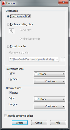
Set the destination for the new 2D block. In this example I will simply insert it back on the same drawing. However a footprint could be exported directly to the Custom Footprint folder from here.

Next you configure the lines. Checking ‘Show’ under Obscured lines will add hidden lines to the footprint.

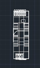
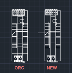
Press Create and verify the new 2D block is as desired.


image  image

I have seen a few other ways to do this type of thing but personally FLATSHOT is my favorite. Its simple yet has a number of options. And its already a part of the software.


Adding Cross Reference (XREF) Info To Footprints – AutoCAD Electrical

$
0
0
imageToday I was asked how to pull cross reference info from the parent symbol into a footprint. This works great on child components. Simply add an XREF attribute to a child component (if its missing) and on placement it auto populates with the parents sheet and reference location. However add an XREF to a footprint and nothing happens to it.
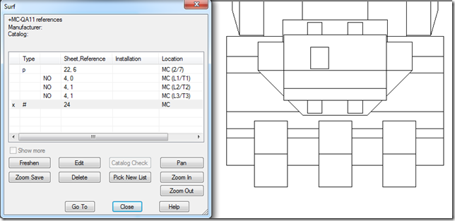
Out of the box, footprints do not pull this information even if the footprint contains an XREF attribute. However this information is available because multiple commands reference the footprints back to the parent symbol. None is more visible than the Surfer

image

In the surfer dialog above we can clearly see a reference between the parent, a child, and the footprint. So the question is, how do we go about getting this information info the footprint?
Below is a nifty utility wrote by Nate Holt back in 2009. (I tested it in 2014 and it still works great) It uses the same calls to the database that the Surfer users to capture this information and then writes it into an attribute named XREF on all the selected footprints.
Simple APPLOAD it and then type the command PANEL_CROSSREF

Add an XREF attribute                 Run the command                   Select the footprint                 Press enter…
image   image  image image

If you don’t like the formatting, it can be changed in the lsp. by modifying this line…
                    (setq cross_ref_str (strcat sheet "/" ref))I highlighted it in red in the code below as well.

Here's the utility:


; ** 24-Mar-09 NEHolt
; -------   P A N E L _ C R O S S R E F . L S P  --------
(defun c:panel_crossref ( / ss active_dwg_INST active_dwg_LOC x tag loc inst
            slen ix ben hit cross_ref_str rec ref str query_data sheet
            termno scratch_fnam panel_xref_attrib_name)
  ; PURPOSE: push schematic parent cross-reference info on to panel footprint
  ;          symbols if target cross-reference attribute is present.
 
  ; Set the target attribute name for this special cross-referencing
  (setq panel_xref_attrib_name "XREF")
 
  ; Get active project's "scratch database" file name
  (if (setq scratch_fnam (c:wd_mdb_get_proj_scratch_dbnam nil))
    (progn ; Now have active project's scratch database filename
      ; Read the active drawing's "WD_M" block values. This will carry
      ; the active drawing's default INST and LOC assignments which
      ; may be needed later.           
      (if (not GBL_wd_m) (wd_cfg_read_dwg_params))
      (setq active_dwg_INST (nth 52 GBL_wd_m))
      (setq active_dwg_LOC (nth 53 GBL_wd_m))     
           
      ; Now prompt user to select footprint and panel terminal symbols
      ; to process.
      (princ "\nSelect footprint and/or panel terminals to process:")
      (setq ss (ssget '((0 . "INSERT")))) ; gather up selected INSERTs
      (if (/= ss nil)
        (progn ; some INSERT instances selected, okay to proceed
           
          ; Begin to process the picked block INSERT instances on active
          ; drawing.
          (setq slen (sslength ss)) ; number of entities picked
          (setq ix 0) ; will be used to index through them
          (while (< ix slen)
            (setq ben (ssname ss ix)) ; get next entity to process
            (setq ix (1+ ix)) ; increment index for next time
            ; Determine what this block insert is
            (setq x (c:wd_is_it_pnl ben))
            (cond
              ((= x "FP") ; panel footprint
                (setq tag (c:wd_get_pnlval ben "P_TAG*"))
                (setq loc (c:wd_get_pnlval ben "LOC"))
                (setq inst (c:wd_get_pnlval ben "INST"))
               
               
                ; if LOC or INST blank, substitute in the drawing-wide
                ; default assignment.               
                (if (= loc "")(setq loc active_dwg_LOC))
                (if (= inst "")(setq inst active_dwg_INST))
               
                ; Call internal "surfer" query function               
                (setq query_data (wd_surfa_getcmprefs (list tag inst loc) nil nil))
                ; Sort through returned data. Look for schematic parent
                (setq hit nil)
                (foreach rec (car query_data)
                  (if (not hit)
                    (progn
                      ; Format of rec will be: (list type par1chld2 nonc ref sheet ? ? ...)
                      ; where type = "1" for schem parent
                      (if (AND (= (nth 0 rec) "1") ; schematic symbol
                               (= (nth 1 rec) "1")) ; and it's a parent
                        (progn
                          (setq hit rec)
                ) ) ) ) )
                (if hit
                  (progn ; Found match. Format the cross reference text
                    (setq sheet (nth 4 hit))
                    (setq ref (nth 3 hit))
                    (setq cross_ref_str (strcat sheet "/" ref))
                    ; Push cross-ref out to target attribute
                    (if (not (c:wd_modattrval ben panel_xref_attrib_name cross_ref_str nil))
                      (progn ; problem
                        (princ "\nNo ")
                        (princ panel_xref_attrib_name)
                        (princ " attribute found on panel footprint ")
                        (princ tag)
                        (princ " for cross-ref ")
                        (princ cross_ref_str)
                    ) )
              ) ) )
              ((= x "FPT") ; panel terminal
                (setq tag (c:wd_get_pnlval ben "P_TAGSTRIP*"))
                (setq termno (c:wd_getattrval ben "WIRENO,TERM01,TERM"))
                (setq loc (c:wd_get_pnlval ben "LOC"))
                (setq inst (c:wd_get_pnlval ben "INST"))             
                ; if LOC or INST blank, substitute in the drawing-wide
                ; default assignment.               
                (if (= loc "")(setq loc active_dwg_LOC))
                (if (= inst "")(setq inst active_dwg_INST))
                ; Call internal "surfer" query function               
                (setq query_data (wd_surfa_getcmprefs (list tag inst loc) nil "2"))
                ; Sort through returned data. Look for schematic parent with same terminal
                ; number value.
                (setq hit nil)
                (foreach rec (car query_data)
                  (if (not hit)
                    (progn
                      ; Format of rec will be: (list type ? ? ref sheet ? termno ...)
                      ; where type = "T" for schem terminal
                      (if (AND (= (nth 0 rec) "T") ; schematic terminal
                               (= (nth 6 rec) termno)) ; match on schem terminal number
                        (progn
                          (setq hit rec)
                ) ) ) ) )
                (if hit
                  (progn ; Found match. Format the cross reference text
                    (setq sheet (nth 4 hit))
                    (setq ref (nth 3 hit))
                    (setq cross_ref_str (strcat sheet "/" ref))
                    ; Push cross-ref out to target attribute
                    (if (not (c:wd_modattrval ben panel_xref_attrib_name cross_ref_str nil))
                      (progn ; problem
                        (princ "\nNo ")
                        (princ panel_xref_attrib_name)
                        (princ " attribute found on panel terminal ")
                        (princ termno)
                        (princ " for cross-ref ")
                        (princ cross_ref_str)
                    ) )
              ) ) )
          ) )
          (setq ss nil) ; release the selection set
      ) )   
  ) )
  (princ)
)  
Download a copy of the file here… https://skydrive.live.com/redir?resid=CE5A96771F5F2F9E!322&authkey=!ACdSIuPSgf0JwuY
To use:     1. You will need to add attribute’s named XREF to all panel footprints and terminal footprints that need this functionality.
     2. APPLOAD the lsp file. Type PANEL_CROSSREF [Enter]. Select all panel footprints to update and press enter.

Mirroring Components the Proper Way – AutoCAD Electrical

$
0
0

Once again I have a someone using AutoCAD commands inside of Electrical and their confused by the results. This time it was AutoCAD’s MIRROR command causing the problem. When using the AutoCAD MIRROR command, the wire connection attributes end up switching sides and future wires will attempt to enter the wrong side of the symbol.

Below the connector has been mirrored using the AutoCAD command and notice how the new red wire now pulls off of it. Its because the wire connection attributes have switched sides.
image

The wires know what direction to go based off of attribute name.
X1TERM0# wires come into the component from the right.
X2TERM0# wires come into the component from the top.
X4TERM0# wires come into the component from the left.
X8TERM0# wires come into the component from the bottom.


The answer is to simply use the correct AutoCAD Electrical command: Reverse/Flip Component
 image

2014 Content update for Rockwell Automation (Allen Bradley)

Toggling Dots to Angles and Back Again

$
0
0

This is a follow up to the <<Swapping Entire Symbol Libraries Project Wide>> post. After switching all symbols from JIC to IEC, the next step could be switching wire connection dots to angle connections.
image image

There is an existing toimageol that does just that. AETOGGLETEE It’s located under the Edit Wires panel.

After starting the command, window select the dots to be converted. Or type ALL and press enter. This selects the entire drawing and converts all connection dots at once. I noticed it only seems to select the dots that are currently on the screen even when typing ALL. So be sure to Zoom Extents first.
Editing this buttons macro to do all dots would be as easy as…
ZOOM E AETOGGLETEE ALL  ^C
(note the space behind the ^C)

So moving from dots to angles is quite easy. How about angles back to dots? Not so easy, but I’ve found a script that does just that.
Download it <<here>> or make your own using the script below.


image

Remember a script can be run project wide from the Project Utilities dialog.

Electrical Humor

$
0
0

It may just be my new fitness routine, but I found this quite funny.
electricity-Resistance
Found on http://physicshumor.blogspot.com/
I can’t read the signature on the lower right so I can’t give credit where its due.

Viewing all 46 articles
Browse latest View live