Quantcast
Channel: Terminal AutoCAD
Viewing all 46 articles
Browse latest View live

I Need More Fields! – Pushing Past The Limits of Title Block Update

$
0
0

Many companies have had to settle with placing some “specific” field in one of the ten default Drawing Properties. It could be as simple as needing a forth description line. Since there are only three default description fields, the forth description line more than likely ends up in the Project Code field.

Another example could be needing semi-project wide descriptions. The Title Block Update utility can become too restrictive in these instances.

I went on a quest to find the easiest way to push ALL title block attributes out to a spreadsheet and then pull the changes, project wide, back into Electrical. As always, please comment or e-mail me if you know of an easier/better way.

After some initial testing, I finally decided to focus on the existing Export To Spreadsheet utility.

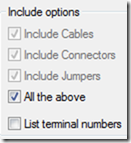
Any block with a TAG1 attribute is exported using the Components option. So simply add an invisible TAG1 attribute with a default of TITLE. Also add another invisible attribute named LOC and add a default value of TITLE. This will allow us to create spreadsheets with only the title blocks.

imageNext we need to create a <<default.wda>> file.  Using the User Attributes command makes creating this text file quite easy. From the Reports tab click on User Attributes and then add all title block attributes to the list. These attributes will now be available in any of the component type reports.

This would be placed in the same support location the title block mapping file (.wdt) was placed in. Some networked support path or inside the active project folder.


image

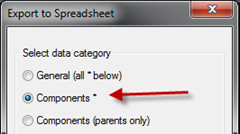
imageThat’s it! We are ready to export all title block attributes project wide. From the Import/Export Data tab select To Spreadsheet. Select Components from the resulting dialog and press OK.
imageimage

The next dialog (Component Data Export) sets the scope of the export. In this case we want Project and a Named Location of TITLE. Pressing Drawing will show the list of locations and TITLE should be listed.

Press OK and specify a location for the Excel file. After opening the Excel file, scroll all the way over to the right and all the User Attributes will be listed with the values pulled from the drawings.

Once all needed changes to the title block attributes are completed its time to import back into AutoCAD Electrical.

Again from the Import/Export Data tab, but this time select From Spreadsheet. It should remember the name and location and simply require the press of the Open button. Worse case you may need to browse back out to the file location.


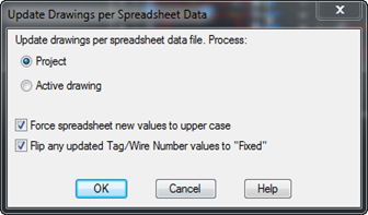
imageThe next dialog has a cool option that will force all spreadsheet values to upper case. Press Project and OK and all new values will update in each sheets title block.
image


The title blocks should not show on any BOM reports because of the lack of catalog information. To exclude them from the Component report place ~TITLE in the location code. This will exclude all blocks with a location of TITLE.


Making Changes to the ENTIRE Symbol Library – AutoCAD Electrical

$
0
0

I noticed this call coming into our support desk today. The user needed to change the scale of every symbol in the entire JIC or NFPA library. That’s quite the task to tackle manually. There are over 1,700 symbols in the NFPA folder with another 133 in the 1- subfolder. The IEC library contains over 3,300 symbols! Opening each and every symbol to simply change a scale or change an attributes text height is an extremely time consuming and monotonous task.

imageInstead of “there’s an app for that,” I can say wait “there’s a utility for that.” It’s slightly hidden. Its under the Symbol Builder button.

Make a backup of the library folder first of all. Then start the Modify Symbol Library utility. After selecting the library folder to modify, the final dialog allows all kinds of changes. Also note the ability to run a LISP expression. So pretty much anything can be done to each and every symbol in the library.
image

How to Make the Previous/Next Arrows Prompt For Save – AutoCAD Electrical

$
0
0
[image69.png]

These arrows are nice to use since they close each previous drawing as the new drawings are opened. However a down side to this automatic functionality is that any changes are SAVED automatically.

This can be good or this can be very bad. The drawings are saved and then closed. So the undo history is lost.

However there is a setting in the wd.env file that can be enabled. Simply find the following row…
*WD_PROMPT_SAVE,1,set to 1 to trigger "Save changes" prompt when using open dwg next/prev arrows buttons

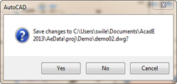
By default this row is commented out (*), and Electrical saves automatically if there are pending changes. Remove the asterisk from this row and the Next/Previous buttons will prompt for a Save if there are any pending changes needing a save. After pressing Yes or NO the drawing will close and move on to the Next/Previous drawing.
image

For more information on the wd.env file see these past posts.
http://myacade.blogspot.com/2012/09/where-does-wdenv-path-get-set.html 
http://myacade.blogspot.com/2013/02/breaking-wdenv-file-down-line-by-line.html

Be Patient More Content Is On The Way…

$
0
0

With AU just around the corner, I have been using any free time I find to work on my presentation. I promise more content is in the works.

Tibetan resistance movementImage used with permission from Laco Mandor Laurincik at http://www.mandor.sk/

Catalog of Posts

$
0
0
I haven’t been that happy with the search feature on this blog lately. Several times in the past few weeks I have been asked for something that I knew I had already wrote about. After several searches, I finally had to resort to looking through ALL the posts until I found it.
Click the read more link to see the entire list.

Automation
Running a LISP, or Command, on File Open - (Fix_Me)
Auto Trim Wires from the PLC I/O Utility
Creating Keyboard Shortcuts in AutoCAD Electrical
Updating All Drawing Settings (Descriptions) Using Excel
Making Changes to the ENTIRE Symbol Library
Cables
AutoCAD Electrical and Inventor – Follow Up
Circuit Builder
Circuit Builder Tutorial Video's
Databases
Controlling What Table Is Selected For Catalog Lookup
Adding the Missing Manufactures to AutoCAD Electrical’s Catalog Database
Easy Simplified Catalog Database
How to import components into Electrical from a spreadsheet
Humor
Shop Tools & Real Definitions
Electrical Humor
The Humor Outlet
Ladders
Changing a Ladder Reference Style Project Wide
Understanding and Customizing Electrical's Ladder Reference Numbers (MLR)
Miscellaneous
How to Check Out (Borrow) a Network License
Mass DWG Save-As Back To An Older Release
Adding the Express Tab to the Ribbon
Always QSAVE, Always QSAVE, Always QSAVE
Translating a Network License File into English
Getting Rid of the ViewCube
Where Is My Open Dialog Box
Presetting The Surfer's Zoom Distance in AutoCAD Electrical
Panels
Adding Cross Reference (XREF) Info To Footprints
Flattening 3D Models Into 2D Footprints – FLATSHOT
Understanding How the Din Rail Spreadsheet (wddinrl.xls) Works
Peer Symbols (HYD, PNEU, P&ID)
Hydraulic, Pneumatic, and P&ID Schematics In AutoCAD Electrical?
PLC’s
Creating a custom PLC style in AutoCAD Electrical
PLC Cards Randomly Adding Additional Lines
Auto Trim Wires from the PLC I/O Utility
Projects
Managing Projects Inside of AutoCAD Electrical
Surfing a Project Using Wild Cards – Fix_Me 2
Closed Project Folders Return After a Restart - lastproj.fil
How to Make the Previous/Next Arrows Prompt For Save
Reporting
Batch Plotting a Project and PC3 files
Adding User Created Attributes to Reports in Electrical
INST & LOC Codes Honor Wildcards When Searching
Creating a Table of Contents or Drawing List Report
Settings and Properties
Where Does The wd.env Path Get Set?
Breaking The wd.env File Down Line By Line
Symbols
Wildcards for Device Tagging and Wire Numbering
Displaying Catalog Numbers On The Symbol
Where are the 2 Pole Components?
Mirroring Components the Proper Way
Swapping Entire Symbol Libraries Project Wide
Modifying Attributes In Existing Blocks
Adding Wire Numbers to Symbols
Wire From/To Annotation On the Schematic
Making Changes to the ENTIRE Symbol Library
Terminal Strips
Title Block Update
Title Block Update - The Basics
Title Block Update - Mapping Project Wide Revisions
Title Block Update - Previous / Next Sheet Numbers
Title Block Update - Merging Multiple Fields Into One Attribute
I Need More Fields! – Pushing Past The Limits of Title Block Update
Updating All Drawing Settings (Descriptions) Using Excel
Wires and Source/Destination Arrows
Wildcards for Device Tagging and Wire Numbering
Putting a Twist on the Twisted Pair Symbol
Using the Wire Gap Feature In Place Of From/To Arrows
Mass Changes to Source/Destination Arrows
Hidden Wires and Wire Numbers
Toggling Dots to Angles and Back Again
Wire Numbers
Hidden Wires and Wire Numbers
Wire From/To Annotation On the Schematic
Company Wire Numbering - Advancing Wire Numbers By One

The Basics of Creating an AutoCAD Electrical Symbol

$
0
0

The Symbol Builder guides you in the making of symbols. Its very easy and quick to create your own “intelligent” symbols. In this post we will look at the basic workflow and some general guidelines used when building symbols.

Starting the Symbol Builderimage

The command is on both the Schematic and Panel tabs. There is no differences in how the command starts, or its options, between the two locations.

Select Symbol Objects and Attribute Templateimage

If the reference geometry is already in block form, it can be selected from the (1) embedded block list drop. If the block is external, it can be selected by pressing the Browse button. The block can also be simply selected using the (2) select objects button.

Any existing geometry, text, and attributes, not in block form, can be selected using the (2) select objects button as well. Nothing is required here since the entire block can be created inside the Block Editor environment.

Tip: Verify the symbols size will match up with the default wire connection spacing for the desired standard. If wire connection spacing is not consistent between symbols extra clean up will be required when swapping blocks.

Specify the insertion point using the (3) pick point button. This can be changed later but it will make working in the Block Editor easier if this is specified now.

Next we choose the proper attribute template (4) The path points is to the default symbol library NOT where you wish to save this block. The attribute blocks are saved there. Just make sure the proper standard is selected. The other two menus narrow down which attribute template will be used. They also aid in naming the block later. A later post will discuss attribute template blocks in more detail.

The preview area (5) should show a little view of the geometry that was selected. If a block was selected the attribute names will show instead of the actual values the attributes hold. Pressing OK opens the Block Editor

imageThe Block Editor

First a quick overview of the Symbol Builders Block Editor environment.

(1) The biggest thing on the Symbol Builder tab is the option to toggle the visibility of the (2) Symbol Builder Attribute Editor panel. Use the Done button once the symbol is complete.

The (2) Symbol Builder Attribute Editor panel is the heart of this little environment. It allows easy insertion of required attributes based on the previously selected attribute template as well as wire connection locations. We will discuss it in detail in the next section of this post.

There is really no reason for the (3) Project Manager. It could be closed and reopened from the Project tab after the symbol creation. The same can be done for the (4) Dynamic Block Authoring Palette. It is used in the creation of dynamic blocks and rarely used in AutoCAD Electrical. It can be toggled back on from the Block Editor tab.

The (5) graphic area is the blocks model space. If additional geometry, text, or attributes are needed, simply switch to the Home tab and add or modify as required. Pretty much anything that can be created in AutoCAD can be created here in the Block Editor environment.

Using the Symbol Builder Attribute Editor

When this palette first came out it had a lot of people really upset. I’m not sure why. From the start I felt this was about 1200 times better then the black box symbol builder dialog. image

Before we get into the attributes, I want to point out this button.  This button opens a dialog that allows a new attribute template to be selected. It also allows a new insertion point to be selected but you will have that option later as well.


Attributes
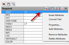
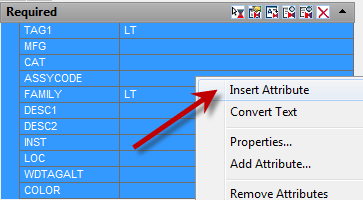
Now onto attribute placement. This is really slick. Simply select the desired attribute and press the first little icon. image If the icons areimage too small for you, right click and all of the same options are available there as well. After choosing Insert, click to place the attribute in the graphics window.  Another way to insert, is to select the desired attribute and then simply click and drag the attribute line into the graphics window. When the mouse button is released the attribute will be waiting for placement.

Note the second option is Convert Text image (third icon). This is a great command when converting existing imageAutoCAD blocks. Selecting text will carry the text formatting into the attribute keeping the same look. A side effect to this is the text value becomes the attributes default value. This can cause a problem if selecting text stating LT100. That will become the new default prefix for all tags when using this symbol. After all attributes are placed, review the attribute defaults before continuing to the next step.

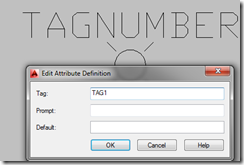
To reuse existing attributes from an existing AutoCAD block, simply double click it and rename its TAG to match a desired attribute line. What do I mean by this? Note the image below already has an attribute for TAG called TAGNUMBER.
image   image
If I rename this original attribute to AutoCAD Electrical’s default TAG1, immediately the TAG1 attribute line is confirmed.
image     image    image

If a symbol has no text to convert and it’s the default size, all attributes can be placed at the same time. Select all of the attributes in the palette and then insert them as a group. The insertion will be based off of the attribute templates origin and where that attribute lives in the template. So zoom out a bit because some of the attributes may be slightly off screen when placing.
image   image
Some attribute templates will have some optional templates that can be placed as well. Remember this is AutoCAD. Place any extra attributes necessary. They can always be edited using the AutoCAD attribute editors and their values can also be used in reports later.

Wire Connections
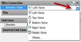
imageWire connections consist of two attributes and could be placed manually. However this utility will place and name them properly for you. Click in the white space beside Left/None and a drop down arrow will appear. Click the arrow and all of the possible wire connections are available for selection. Choose one and then press the little icon image above it to place a new connection in the graphics window. Remember to use OSNAP’s when placing these connections. (Shift+Right Click) The wires will end on the attributes insertion point not the geometry being selected.


If a series of connections is needed simply keep clicking. Wire connections will continue to be placed. Remember to switch connection types as needed or wires will not connect properly. imageimage

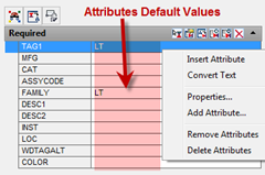
If this symbol will always receive the same pin numbers, they can be called out here in the attribute default area.


Link Lines
image

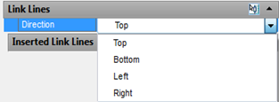
Dash linked lines are setup pretty much the same as wire connections. Make sure to add all possible directions for the symbols needs.

In the example below, you can see the need for both sides of the connection in most symbols needing link lines. The exploded blocks on the right are copies of the linked selector switch on the left. The link line attributes are shown on the image on the right.


image     image

Close Block Editor: Saving the Symbol

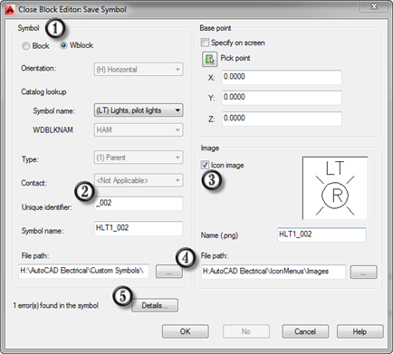
Ok so that’s about it for the basics. How bout we turn this into a block and test it? From the Symbol Builder tab select Done.
image

Once again note the ability to set the base point. The insertion point should be set by now but if not this is the last chance.

Choose if this block should be (1) imbedded in this drawing only (block) or wrote to an external dwg (wblock). Then we move on to naming the block. The symbol prefix is already taken care of. Simply update the (2) unique identifier field and then click/tab out of the field. This will cause the bock and image name to update. If no icon image is needed, clear the check (3) for icon image.

The (4) file paths should be set by the wd.env file. Even so verify the paths are pointing to the proper locations.

Finally review the errors found by the block audit by pressing the (5) Details button.

After pressing OK you are given the option to insert the block after closing the block editor. The correct answer here is Yes. Verify that the wire connections work and attributes are in their proper location. If not, take the block right back into the Block Editor and fix the problem.

image

Symbol Building Beyond the Basics – AutoCAD Electrical

$
0
0

In this post we will walk through the steps needed to create something more complex. I was thinking of a block for the Rockwell Turbo-Encabulator. However Jason Moore has been waiting patiently for a Rockwell Power Flex 40 AC Drive block for over three months now. Oh well, I wasn’t sure how I was going to draw the six hydrocoptic marzlevanes anyway.

imageJason and I discussed using the parametric PLC symbols but decided it would change the look too much and be more work then necessary for this single block.

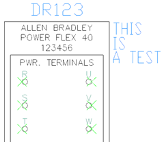
So here is our starting AutoCAD geometry (on the left). Currently it is all simple geometry and text. No blocks or attributes. It has already been broken into two halves so lets start with the top half by taking it into the Symbol Builder. image
Start the Symbol Builder command. image  Select the geometry from for the top of the drive. I choose the left quadrant of the “R” terminal as my insertion point. That should make it easier to place into exiting wires rather than using the upper most corner of the block as the insertion point.

STOP! If your confused by this point, you need to stop reading this post and go read this one first….  The Basics Of Creating A Block I do not plan to show the basics of each dialog again in this post. Instead I want to focus on little tips and tricks that can be applied here to help make the end users job easier.

Since drives (DR) do not have a standard attribute template simply use the generic (GNR) one. That should be all that’s needed before pressing OK and moving into the Block Editor environment.
image

Placing The Attributes

I plan to start at the top of this block and work down. First thing is to place the needed attributes. Below you can see TAG1 and the DESC attributes have already been placed. I went into the properties palette to modify the justification of the DESC attributes. To make the MODEL NUMBER text always display the catalog number, use the Convert Text option.
image

However after converting the text be sure to remove the default value (See image below). Anytime text is converted the original text becomes the attributes default value. Most of the time this needs to be modified or removed. In this case I’ll remove the entire value. Also the CAT attribute is invisible by default. In this case we want it to display. Using the Properties palette toggle Invisible to No.
image

Before we move on away from the attributes, be sure to set the default FAMILY attribute to DR. This will make sure the catalog defaults to the Drives (DR) table.
image

Placing Wire Connectionsimage

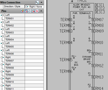
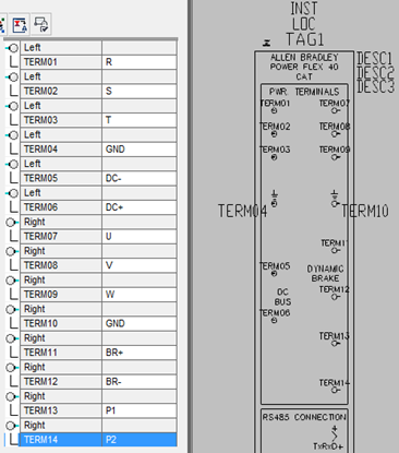
Next we place the wire connections. From the image on the right, you can see I placed all of the terminals on the left and then, after switching direction, placed all of the right connections.

Since these terminals all seem to have standard letters/numbers, lets make the terminals take on those as defaults. Select each terminal’s attribute in the palette and then choose Convert Text, then select the proper terminals id. This copies the location and formatting of the original text. Pretty cool!
imageimage

imageFor the ground terminal, since I can’t use a symbol, I chose to use GND and simply make the attribute invisible.
image
Finish up the rest of the terminals.

Dynamic Clean Up

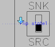
That takes us down to the DIP switches. Since this symbol will be for multiple drives, lets make these switches actually functional using a Dynamic Flip function. More than likely you have closed the Block Authoring palette by now. It can be opened again imagefrom the Block Editor tab.  For the switches the Flip parameter imagemakes the most sense. If you are unfamiliar with Dynamic Blocks a Flip is a good place to start. Simply follow the prompts. In this case the Flip Parameter is setting the mirror line for the flip/mirror. Once the Parameter has been placed, I used the move command and moved it off to the side a bit. Just be sure to not move the the Parameter up or down because doing so would change the mirror line for the Flip Action.
image

imageAfter placing a Parameter, its time to place an Action. Switch to the Action tab on the Block Authoring palette and choose the Flip image Action. Actions always start with selecting what Parameter the Action is to be associated with. So select the Flip Parameter and then select the geometry that is to flip. Then right click to continue. Done.

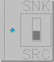
Dynamic additions to bocks are so easy and add so much functionality. Do the same to the switch on the other side. Anytime your working with Dynamic Blocks, its good to test the Parameters/Actions before before leaving the Block Editor environment. There is a handy tool on the Block Editor tab imagethat does just that. Inside the test environment, select the block to display the dynamic handles. Note the Flip arrows. If you placed the Parameters and Actions properly the switches should change position by simply clicking the Flip arrows.
image image image
To leave the test environment press the  Close Test Block Window button.image

imageThat should finish up this block. We added the needed attributes, wire connections, and ended with a little Dynamic Block action.

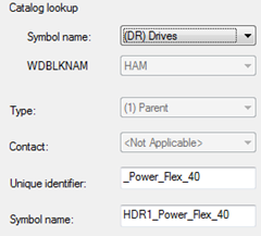
Exit the Block Editor environment using the Done button on the Symbol Builder tab. Since we chose Generic as the type at the start of this process, be sure to change the Symbol name drop down to Drives. That will update the block name to DR. Also modify the Unique identifier as well. Be sure to verify, and change if necessary, the icon and symbol save paths. image

Then place the symbol and verify the attributes and wire connections work as expected. On the right is my test symbol. The catalog attribute is working as well as the wire connection points.

If all is well, add the symbol to the Icon Menu.

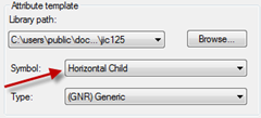
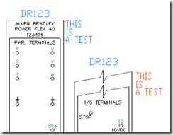
But that’s not all. That was only the top half. Lets start the process over for the bottom half of the drive symbol. The only difference between the two pieces of this block, is setting the bottom half as a child. How you do that is easy. Simply choose the Horizontal Child attribute template before entering the Block Editor environment.
image

Place the attributes, wire connections, and add some more flip actions to the bottom half of the drive and we’re done. I chose the same Unique identifier keeping the two block names the same except for the fourth character. Parents fourth digit are a 1 and children are 2’s. image

Place and test the child block. Link it to its parent and the relationship should be established and the parent attribute values should carry across.

imageI hope this post demonstrates how easy it is to turn any existing AutoCAD geometry into intelligent AutoCAD Electrical symbols.

I have recorded the entire process I used making these blocks and it will eventually be posted to IMAGINiT’s YouTube channel. I’ll post a direct link here as well once its up.

MyACADE’s 2013’s Blog Stat’s

$
0
0

I’m not sure if its me being an engineer, or me being a true nerd, but for some reason I’m fascinated by the stats that can be created from a webpage. Below are a few interesting things about this blog from last year. All statistics are shown for the year 2013 only.

Total blog (not page) visits: 8,309
Directly entered web address (not referred): 29.10%
From a search engine (Bing, Google, ect): 21.87%
Mobile and tablet traffic: 4.39%

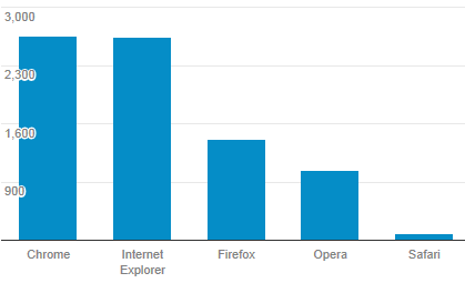
Visits grouped by browser:
image

Number of new posts: 37
My official (posted) goal was 24 posts for last year. My personal goal was 52. I’m not sure if 37 is a win or not.

Most active blog post: AutoCAD Electrical 2013 New Features! (2,210 Views)
Breaking The wd.env File Down Line By Line (908 Views)
Wire From/To Annotation On the Schematic (694 Views)
Creating a custom PLC style (620 Views)
Title Block Update - Previous / Next Sheet Numbers (604 Views)

Number of new people I have personally met because this blog: 2

Number of pages viewed per blog visit:
image

Average time (in minutes) spent per page visited:
image

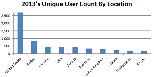
Visits by location:
image

Top ten locations:
image

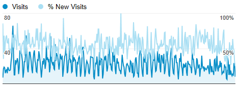
Percent of new viewers vs returning viewers: 54.36% New on Average
image

This years visits per day
The dips are weekends.
image

I hope you enjoyed this useless information. I have a series of reporting posts in the works.


Overview of Reports in AutoCAD Electrical

$
0
0

There are three types of reports in AutoCAD Electrical. Schematic, Panel, and the Drawing List report.
image        image
Schematic reports only pull values from schematic symbols on the drawings in the project. Panel reports only pull values from the panel footprints. However the Panel report has an option (Full) that will include all values from ALL components. The Drawing List report uses the data stored in the project descriptions and drawing properties. Of course a few other types could be added to the list if the audits and export options were included.

Reports are broken down into the following categories. Each of the categories come with their own options, sorting, and reportable properties list.
image    image

The Basics

All of the reports allow project wide as well as active drawing wide reporting. Project wide isn't necessarily all drawings. A separate drawing selection dialog opens to allow selection of individual drawings as needed. Most of the reports also have an option for a manual selection (pick) of components to report on.
image

  • Note: If “Active drawing” is not available it is more than likely because the drawing is not a part of the active project. Any Project report, in this case, will be from the active project and NOT the project the active drawing is from.

Filtering by Installation or Location Code can further limit the components being reported on. This filtering is far more powerful than single values. See the blog post about wild cards to see how to include/exclude multiple values.
       INST & LOC Codes Honor Wildcards When Searching
image

Typically there are a number of report type specific options in the middle of the Reports dialog.
image

All of the report types have a Format button. image Pressing this button opens a new dialog that allows the user to select a report settings (.set) file. The .set files store formatting and selection options. These are created from the Report Format Setup command.
image

The Report Generator
image

The Report Generator shows a preview of what records will be reported and what data about each record will be included. Here header information can be added, sorting and grouping can take place, and columns can be added or removed from the table. The User Post button allows scripts to run on the data. Typically there are one or two scripts already provided under User Post for the different types of reports.

Finally either Put on Drawing or Save to File is pressed. Put on Drawing brings up a table wizard that allows control of the report table formatting. Save to File gives the following file types as exports.
image

Updating Existing Reports

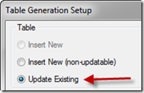
Currently reports are not updated automatically as changes are made to the schematic. Simply rerun the report and then choose Place on Drawing. If that report was already placed somewhere in the project, the Table Generation Setup will default to Update Existing. Simply press OK and any changes will update in the existing table.
image

When saving the report out to a file, saving a new report export can save over the old export. (Electrical will prompt stating a file will be overwrote) Just be aware of this because any changes made to the original export will be lost as the new file completely saves over it.

I have several unique report configuration requests that will follow this post.

My Working Vacation

$
0
0

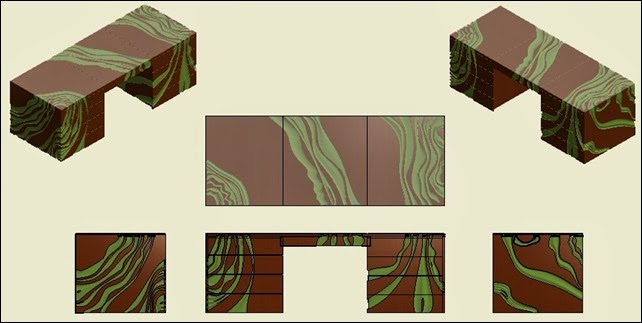
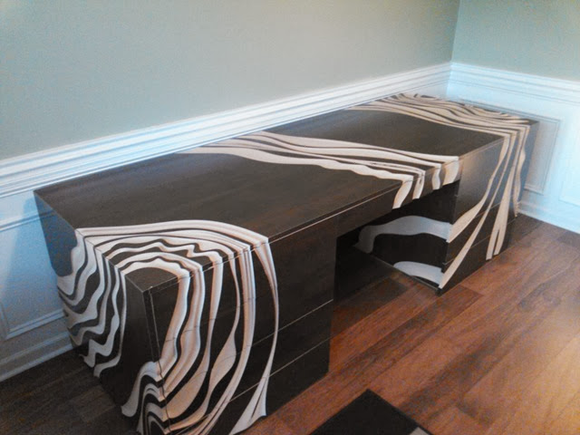
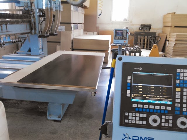
I took a week and a half off this month. My vacation goal was to build an office desk/work bench. I had this idea in my head but really nothing on paper. I started on the Inventor model on Saturday last week and today finished the desk. I had no idea this project would involve so many people and I’m deeply grateful to all that helped. Technically this desk is not 100% complete. I have a good bit of sanding and painting on the routered grooves left to do. However I was so excited by the final results I had to share them.

Inventor Print..
Office Work Bench

Finished design (before paint) The plan is to have the grooves the same color green as the walls.
2014-03-01 18.03.42

2014-03-01 20.51.53

Before more pictures, I would like to give a huge thank you to my parents for helping transfer and the pieces from OH to SC and for all the help assembling once it was home. Also a huge huge shout out to Dean and Wayne at Wengerd Wood for all the routing and CNC programing time.

Production Photos

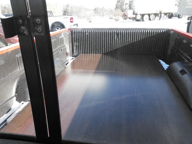
Three sheets of 3/4 inch cherry veneer MDF coming home from the finishers. We bought the wood from Kiem Lumber but I can’t remember the name of the finisher.
2014-02-26 09.17.10

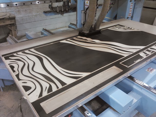
First sheet on the router. I must say, I was a bit nervous as the bit first cut into it.
2014-02-26 13.18.53

Tabletop and middle front just about finished.
2014-02-26 19.49.24

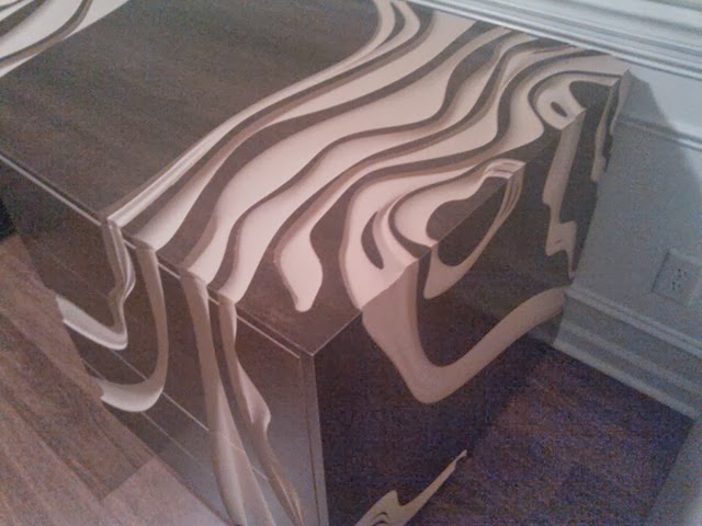
The grooves vary from 1/8th to nearly 3/4 inch deep.
2014-02-26 18.59.27

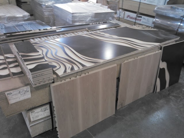
All the parts finished ready to be wrapped up to head to SC.
2014-02-27 12.14.47

Consistent Reporting in AutoCAD Electrical Using (.set) Settings Files

$
0
0

It can be a real pain setting up reports because the reported fields and formatting resets to default with each new report. I have seen users save a report as a template, and then insert the sheet into the project, as a way of controlling the reports format. However the following can be saved as a .set file and referenced on future reports.

  • The various include/exclude report options depending on report type
  • Display and grouping options
  • Predefined filters in the Location/Installation fields
  • Special break and header information
  • Predefine the output type
  • What fields are displayed and their order
  • The “Put on Drawing” options like column width, text color, layer to be used ,ect.

Like most other external files in AutoCAD Electrical, these are simply text files and as such could be edited using a simple text editor. However their format can be quite confusing. The Electrical dialogs for creating/editing these files is defiantly the way to go when creating or modifying saved report formats.

Saving Report Formats

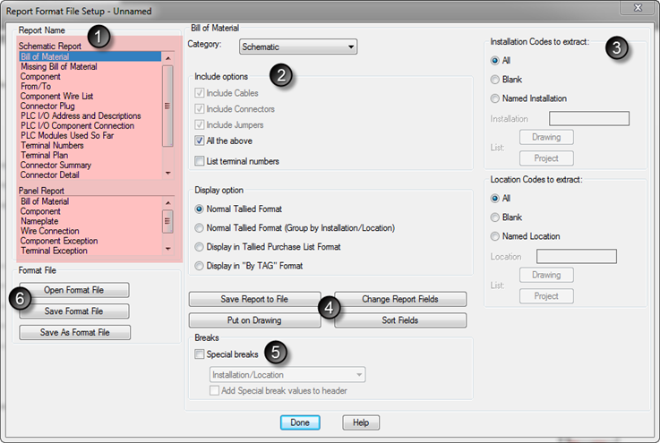
Create these .set files using the Report Format Setup dialog. Its button is on the Reports tab. image The dialog is quite busy. Here is a quick breakdown of its features.
image

  1. Start here. Choose the type of report and all options on the right update.
  2. Review and select any report options. This area is mostly include/exclude and grouping type options.
  3. This section allows filtering by Installation and Location codes.
    1. For more information on the power of these codes see this post. INST & LOC Codes Honor Wildcards When Searching
  4. Options for type of report export, what fields are reported and in what order. To give an idea what what options are hidden behind the four buttons I have included screen shots of each.
    • Save Report to File
      image
    • Put on Drawing
      image
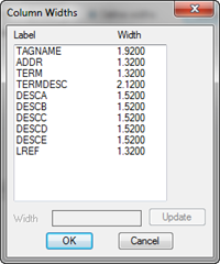
      also note the Column Width “Define” option…
                            image
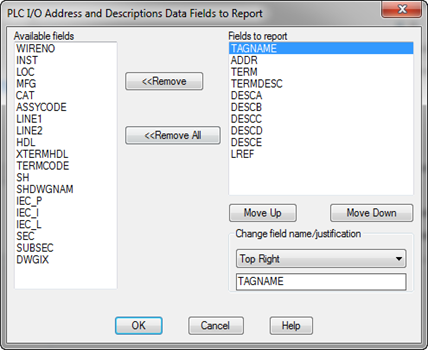
    • Change Report Format
      Of course the fields available are determined by the type of report chosen. Also note the field name and justification can be modified here for each selected field.
      image
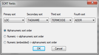
    • Sort Fields
      image
  5. Each report type can be broken into separate tables based on various fields such as location code, manufacture name, block filename, ect.
  6. This is where the options selected are finally saved into a settings file. Pressing Save Format File will prompt for imagea filename if not yet named. Open Format File will load all selected options after opening an existing .set file. And finally Save As Format File will prompt for a new name and not overwrite the loaded .set file. The loaded .set files name is displayed in the top right corner of the Report Format File Setup dialog.

    When opening settings files, only .set files for the currently selected report type are displayed. However when saving, all .set files are displayed to keep from overwriting any other setting files.

.SET File Default Location

The default location for the settings (.set) files is buried in a hidden folder under each users name.
C:\Users\swile\AppData\Roaming\Autodesk\AutoCAD Electrical 2014\R19.1\enu\Support\User\…

However this location can changed in the wd.env file on line (*WD_SET_FILES,x:/some path/,folder for report ".set" files) Remove the asterisk (*) from the front of the line and then replace the path with your own shared network path.

Referencing the Saved Report Settings

Now that a .set file has been created lets use it. Both the Schematic and Panel Reports dialogs have a Format button that allows selection of any .set file for the currently selected report type. If you are not seeing the .set file desired, double check that the correct report type is selected.
image

These settings files are also used with the Automatic Report Selection tool. I’ll try to cover that in a future post.

What’s New in AutoCAD Electrical 2015

Mass Migration of DWG Files Using AutoCAD Electrical

$
0
0

imageOver the weekend I ran into a case where I had several thousand DWG files that were older than AutoCAD Release 14. Vault would not rename them because of this. Inventor’s Task Scheduler wouldn’t migrate them for some reason either. After a few other attempts to migrate, I was running out of options. Then I noticed AutoCAD Electrical on one of the workstations! I checked all of the files out to that workstation, and then used the Modify Symbol Library utility to basically do nothing more than save each DWG.


The Start button remains greyed out even after checking the “Do a SAVE even if no change” box. The dialog wants some actual work. So I had it Zoom Extents on each drawing and that satisfied the dialog. This ran extremely fast! Much faster that Inventor’s Task Scheduler would have. We ran through several thousand DWG’s in under 30 minutes! Of course this workstation is running on SSD’s but still…

image

Show Me Again–Turning Hidden Messages Back On

$
0
0


image

I actually taught an Electrical class again! After being buried under a huge project since last August, it was good to get back into AutoCAD Electrical again. If you follow this blog even the slightest bit, you noticed my lack of posts over the past few months.  From my class, I kept a list of things that I thought would make good blog posts. Here is the first one from the list.

When first entering the catalog lookup dialog, the data is filtered by some defaults. Mark Flayler tells us how that default filter works here…
http://blogs.rand.com/manufacturing/2010/10/autocad-electrical-change-default-catalog-lookup-filters.html

imageClear these filters from the dialog by simply pressing the clear filters button. However after pressing it, a pop up asks if you are sure you want to clear the filters.

In class this week I suggested an engineer check the “Do not show me this again” box. He was hesitant and I suddenly realized I haven't a clue how to get that dialog back once the box is checked.
Lucky for me he didn’t ask. Winking smile


However, later I dug though the AutoCAD Options and just couldn’t find it. I finally discovered, the option to turn it back on is only present if you have checked the “Do not show me this again” box. I would guess there are a number of others that would appear here as well.

image

Hiding Location (LOC) and Installation (INST) Codes Project Wide

$
0
0
image

There is a check box in the Project Properties that will hide any LOC or INST code that matches the Drawing Properties codes. When first checking this you will be informed of the following alert…
image

If the Drawing Properties codes ever change, a Component Cross-Reference is all that is needed to update the LOC/INST visibility again.
image

But I want them ALL hidden!

So the build in tool only turns off the visibility if the values match the drawings same code. What if all location and installation codes need to be hidden? Well the easiest way would be to simply turn off their layer. It’s LOC by default. The layer names are set on the last tab of the drawing and project properties. imageimage

Checking the Freeze check box here will freeze the layer on the drawing. For some reason these boxes are not available on the Project Properties side.

This is really no different then using the standard AutoCAD Layers tools. It simply freezes the layer.

However this doesn’t help someone with a 60 page project who was just told to hide all location codes project wide. This would require manually opening 60 pages and then involve several additional clicks on each page.

This is still an easy fix but requires making a simple script file. Open Notepad and create the following. Note the two extra enter presses. The first is to get out of the layer selection part of the command. The second is to end the command.
I would normally post a link to an uploaded copy of any script… but I think you can handle this one.
image

Now to run the script project wide. Make sure the project is the active project and then load the Project-Wide Utilities from the Project tab.
image


AutoCAD Electrical IdeaStation Is Here!

$
0
0

http://forums.autodesk.com/t5/ideas/v2/ideaexchangepage/blog-id/37/tab/most-recent 
image

Ever wished for a much needed feature inside of AutoCAD Electrical? Or maybe you have an idea for some added functionality to an existing feature… Now you have a direct link to the team working on future releases. Use the link above to access the Electrical IdeaStation and start posting your requests. Or review the existing requests, add your feedback, or simply give some ‘Kudos’ to add some weight to a topic.

Linking the Schematic to the Drawing’s Sheet Number

$
0
0

Wouldn’t it be nice if changing the order of the sheets in the project didn’t screw up the ladders, components, and wire numbers? If your drawings follow a numbering scheme that is directly tied to the sheet number, it is time to update a few property settings.

What things are tied to sheet number in this type of numbering scheme? Well there’s the ladder rung numbers for one. Then we have the components tag finally the wire numbers.

Lets start out creating a new project. I’ll go over modifying an existing project at the end of this post.

The Ladder

imageBefore the ladder is placed, the style needs to be selected from the drawing’s properties.

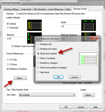
From the Drawing Format tab, select Setup. This new dialog allows us to set ‘Sheet and numbers’. After choosing this setting, place the ladder, or ladders, on the sheet. Remember that the sheets number will be in front of each rung. So the starting rung number will be 00 or 01.
image

If no sheet number has been placed on the current sheet, the rung numbers will start with question makes. Add a sheet number to the drawing and watch the ladder update. Pretty sweet right? Wait until the components and wire numbers updates as well.

image  image
We can’t stop here. Because the rungs are actually named 00, 01, ect. So components and wire numbers will be missing the sheet numbers and that would lead to duplicates.

Note: If the drawing had a sheet number and it is blanked out, the rung numbers are given two zeros in place of the question marks.

The Components

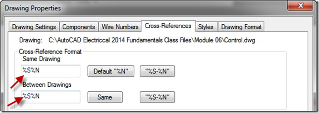
To update this numbering style on the components, it’s back to the Drawing Properties. This time we are adding a %S between the %F (family) and %N (reference number). So the number is %F%S%N or Family, Sheet, Reference Number. All with no spaces or extra characters. Make sure these letters not in lowercase.
image
While we are here we can take care of the cross-reference style as well. Here we do not need the family but do need to add the sheet number (%S).
image

If the sheet number is blank, the component will have question marks in place of sheet numbers just like the ladder did. However unlike the ladder, the component tags do not automatically update after a sheet number change. To update the components tag, simply run the ‘Retag Components’ command.

image imageimageimage

If there are existing cross-references that should be updated as well, be sure to run the Component Cross-Reference command to update these cross-references to match the new style.
image

The Wire Numbers

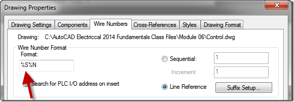
And finally we have the Wire numbers. By now you should know where we are headed. Back to the Drawing Properties again. This time the Wire Numbers tab. Simply add the %S to the front of the Wire Number Format cell and we’re done.

image

Wire numbers are easy. If they are already placed, simply rerun the Wire Numbers imagecommand again and they update. Either way, run the Wire Numbers command.

image

With these settings the drawings can be placed in any order at any time. Simply update the sheet numbers manually, using the Title Block Update, or the Project Wide Update/Retag commands. Then rerun the ‘Retag Component’, ‘Component Cross-Reference’ and ‘Wire Number’ commands Project Wide to refresh the sheets to match the new numbers.


Updating an Existing Project to Reference Sheet Number

The component tags and wire numbers are easy. Simply follow the instructions above and then run the ‘Retag Component’, ‘Component Cross-imageReference’ and ‘Wire Number’ commands Project Wide to refresh existing components.

All of these can be run at the same time using the Project Wide Update/Retag command. But that’s a blog post for another day.


The big problem with changing an existing project to this new numbering style is the ladders. The %S%N is actually a different MLR (Master Ladder Reference) block that the ladders use. So changing the ladder style in the drawing properties will not update the existing ladders. I wrote a post on swapping MLR blocks here… Changing a Ladder Reference Style Project Wide

Adding a Category (Family Table) to the Catalog Database

$
0
0

This command is a little hidden. It’s under the Other Tools drop down off of the Project tab. image

image


In this post I’ll add a category named AT for my “test.” First we confirm that AT is missing from the category drop down. (Image on left)


image
The command first asks what database you wish to modify. Choose your current default_cat.mdb.

Type in the new Category code and its description. This will create the table as well as modify the _FAMILY_DESCRIPTION table.

image   image

And of course we need to verify that the new category is actually there…
image

Uninstalling the Autodesk Design Suites

$
0
0

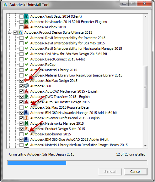
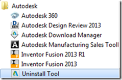
Over the weekend I sat down to write a post about setting default pin values. In the process I found I forgot to install all of the manufactures. So I ran through the setup to add them. <<Adding Missing manufactures>> However during the setup process my workstation blue screened. After that, I could no open Electrical, after a profile error, it would switch over to AutoCAD Mechanical for some reason. I uninstalled it but the uninstalled failed halfway through and it was then missing from my uninstall list. I could also no longer install. Half way through the installer it states something about the software already being installed and it rolls the installation back off. I decided to uninstall EVERYTHING 2015 so I could clean out ALL 2015 user folders and the registry. That brings me to the uninstaller. Rather than uninstall all 20+ pieces of software that come with the Product Design Suite there is a nifty uninstaller.Uninstall2

Uninstall0

This tool is nice because it uninstall the software all at once and in the proper order. In the image to the right you can see Backburner and 3ds Max Populated Data are removed ahead of 3ds Max. Pretty cool.

After doing some cleaning using the following pages as references…
Clean uninstall of Inventor 2015
Clean install of AutoCAD Civil 3D 2015
I was able to properly reinstall the entire Product Design Suite again.

I also found these two links…
How to remove all Autodesk products from a Windows system

How to manually uninstall the product using Microsoft Fix it
I didn’t see this option until the full uninstall was in progress. This looks like a much better option. If this option works for you please comment below letting us know.

I could find no clean uninstall instructions for Electrical alone or the entire 2015 Product Design Suite.

So not the post I originally planned on but a post that I hope helps someone out there.

Working with Multiple Level Terminals – AutoCAD Electrical

$
0
0

As multi-level terminals grow in popularity, we continue receiving questions about how to make them work in Electrical. Multi-level terminal blocks are unique in that they are represented by multiple schematic symbols but have a single BOM entry and panel footprint.

There is nothing special about the blocks or footprints. The real magic happens in the database. There are a number of extra fields in the default.cat.mdb that store the extra information needed for associating the different levels together.

The Properties

Lets first look at the properties. In this document I am using AutoCAD Electrical 2015. If you have 2014 or older, you will have a slightly different method for getting to these properties. I’ll post some screen grabs at the bottom of this post that show the older tools.

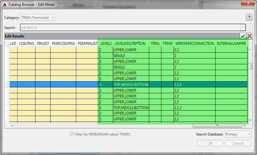
Simply edit a terminal and press Catalog Lookup. Then press the “Edit” button image and scroll all the way to the right.
image

Here you can see the additional properties dedicated to multi level terminals. Modifying them is quite easy. Simply enter the number of levels in the LEVELS cell and then click the image button to open the edit terminal property form. Enter all known information and press OK.
image
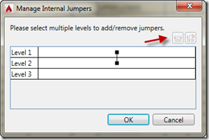
To add/modify internal jumpers between the levels, click on the INTERNALJUMPER cell then click the image button. Select the levels to jumper and then press the Assign Jumper button.
image

The Workflow for Associating Terminal Levels Between Symbols

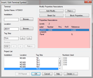
imageThere are a number of ways to create the association between the terminals. In this short tutorial I will only show one. After the symbols have been placed, edit one of them. If multiple levels are present they will be listed in the Edit Terminal dialog.

If no additional levels are present, press Details >> button, and then Catalog Lookup and select a multi-level terminal block.

To create level associations press the Add/Modify button.
image

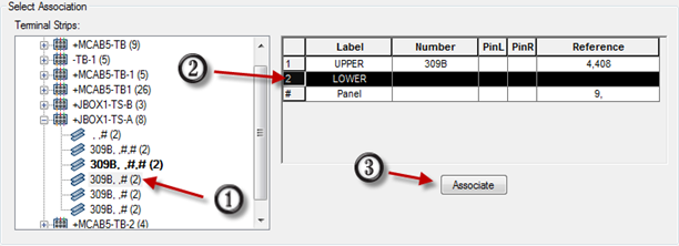
From the resulting dialog, select the terminal you wish to associate, then click the level to add it to, and finally press the Associate button.

image

After the level associations are created, the order of the levels can be modified by using the Move Up and Move Down buttons.
image

That’s pretty much it. If this was too confusing, or involved too much clicking, terminals can be associated using the right click menu as well. Simply right click, Associate Terminals, and then click the “other” terminal.

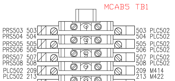
Placing/Updating the Terminal Strip will show the new associations.
image

Terminal Properties For AutoCAD Electrical 2014 and Previous Users

Edit the terminal properties by using the Terminal Properties Database Editor. Look at existing multi-level terminals and note the format needed for each field. (for example 2,2,2)
image

Viewing all 46 articles
Browse latest View live